Inventory of common problems in RF circuit design
In actual design, the real practical trick is how to trade off these guidelines and laws when they cannot be accurately implemented due to various design constraints.
Of course, there are many important RF design topics worth discussing, including impedance and impedance matching, insulating layer materials and laminates, wavelength and standing waves, etc. Careful planning under the premise of a comprehensive grasp of various design principles is the guarantee of a successful design the first time .
1. Common problems in RF circuit design
1. Interference between digital circuit modules and analog circuit modules
If the analog circuit (RF) and the digital circuit work separately, each may work fine. However, once you put the two on the same board and work together from the same power supply, the whole system is likely to be unstable.
This is primarily due to the fact that digital signals frequently swing between ground and the positive supply (>3 V), and with extremely short periods, often on the order of nanoseconds. Due to the larger amplitude and shorter switching times. These digital signals contain a large number of high-frequency components independent of the switching frequency. In the analog part, the signal transmitted from the wireless tuning loop to the receiving part of the wireless device is generally less than 1 μV.
Therefore, the difference between the digital signal and the RF signal can reach 120 dB. Obviously. If the digital signal cannot be well separated from the radio frequency signal. Weak radio frequency signals can be corrupted, and as a result, the wireless device’s performance will deteriorate, or even not work at all.
2. Noise interference from power supply
RF circuits are quite sensitive to power supply noise, especially to glitch voltage and other high frequency harmonics. Microcontrollers draw most of their current in short bursts during each internal clock cycle, since modern microcontrollers are manufactured on a CMOS process.
So, assuming a microcontroller is running at an internal clock frequency of 1MHz, it will draw current from the supply at this frequency.
If proper power supply decoupling is not taken, it will cause voltage glitches on the power line. If these voltage spikes reach the power supply pins of the RF part of the circuit, it may cause work failure in severe cases.
3. Unreasonable ground wire
If the ground wire of the RF circuit is not handled properly, some strange phenomena may occur. For digital circuit designs, most digital circuits function well even without a ground plane. And at RF frequencies, even a very short ground lead acts like an inductor.
Roughly calculated, the inductance per millimeter of length is about l nH, and the inductance of a 10 toni PCB line at 433 MHz is about 27Ω. Without a ground plane, most ground traces would be long and the circuit would not behave as designed.
4. Radiation interference from antennas to other analog circuit parts
In PCB circuit design, there are usually other analog circuits on the board.
For example, many circuits have an analog-to-digital conversion (ADC) or a digital-to-analog converter (DAC). The high-frequency signal from the antenna of the RF transmitter may reach the analog signal of the ADC. If not handled properly at the ADC input, the RF signal can self-excite within the ESD diodes at the ADC input. Thus causing ADC deviation.
Second and five experience summaries
1. Principles of RF circuit layout
When designing RF layout, the following general principles must be met first:
(1) Isolate the high-power RF amplifier (HPA) and the low-noise amplifier (LNA) as much as possible, simply put, keep the high-power RF transmitting circuit away from the low-power RF receiving circuit;
(2) Make sure that there is at least a whole piece of ground in the high-power area on the PCB, preferably without vias on it. Of course, the larger the copper foil area, the better;
(3) Circuit and power supply decoupling is also extremely important;
(4) The RF output usually needs to be far away from the RF input;
(5) Sensitive analog signals should be kept as far away as possible from high-speed digital signals and RF signals;
2. Physical partition, electrical partition design partition
It can be decomposed into physical partition and electrical partition. Physical partitioning mainly involves issues such as component layout, orientation, and shielding; electrical partitioning can be further decomposed into partitions for power distribution, RF routing, sensitive circuits and signals, and grounding.
1) We discuss the physical partition issue:
Component placement is key to a good RF design, and the most effective technique is to first fix the components that are on the RF path and orient them to minimize the length of the RF path, keeping the input as far away from the output as possible Ground separates high-power circuits from low-power circuits.
The most efficient board stacking method is to arrange the main ground plane (main ground) on the second layer under the surface layer, and to run the RF line on the surface layer as much as possible. Minimizing via size on the RF path not only reduces path inductance, but also reduces virtual solder joints on the main ground and reduces the chance of RF energy leaking to other areas within the stackup.
Physically, linear circuits like multistage amplifiers are usually sufficient to isolate multiple RF regions from each other, but diplexers, mixers, and IF amplifiers/mixers always have multiple RF/IF Signals interfere with each other, so care must be taken to minimize this effect.
2) RF and IF traces should be crossed as much as possible, and a ground should be separated between them as much as possible:
The correct RF path is very important to the performance of the whole PCB board, which is why component layout usually takes up most of the time in mobile phone PCB board design.
In mobile phone PCB board design, usually the low noise amplifier circuit can be placed on one side of the PCB board, while the high power amplifier is placed on the other side, and finally they are connected to the RF terminal and baseband processing on the same side through a duplexer on the antenna at the receiver end.
Some tricks are needed to ensure that the through vias do not transfer RF energy from one side of the board to the other, a common technique is to use blind vias on both sides.
The adverse effects of through vias can be minimized by arranging them in areas on both sides of the PCB that are free from RF interference.
Sometimes it is not possible to ensure sufficient isolation between multiple circuit blocks. In this case, it is necessary to consider the use of metal shields to shield the RF energy in the RF area. The metal shields must be soldered to the ground and must be kept in contact with the components. An appropriate distance, thus taking up valuable PCB board space.
It is very important to ensure the integrity of the shield as much as possible. The digital signal lines entering the metal shield should go to the inner layer as much as possible, and it is best that the PCB layer below the wiring layer is the ground layer.
The RF signal line can go out from the small gap at the bottom of the metal shield and the wiring layer at the ground gap, but as much ground as possible should be distributed around the gap, and the grounds on different layers can be connected together through multiple vias .
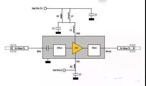
3) Proper and effective chip power decoupling is also very important:
Many RF chips integrating linear lines are very sensitive to power supply noise, often requiring up to four capacitors and an isolation inductor per chip to ensure that all power supply noise is filtered out.
An integrated circuit or amplifier often has an open-drain output, so a pull-up inductor is needed to provide a high-impedance RF load and a low-impedance DC source, and the same principle applies to decoupling the power supply across this inductor.
Some chips require more than one power supply to work, so you may need two or three sets of capacitors and inductors to decouple them separately. Inductors are rarely placed in parallel, because this will form an air core transformer and induce mutual interference. signals, so they should be spaced at least as high as the height of one of the devices, or arranged at right angles to minimize their mutual inductance.
4) The principle of electrical partition is generally the same as that of physical partition, but it also includes some other factors:
Certain parts of the phone operate at different voltages and are controlled by software to extend battery life. That means the phone needs to run from multiple power sources, which creates even more problems with isolation.
Power is typically brought in at a connector and immediately decoupled to filter out any noise from outside the board before being distributed through a set of switches or regulators.
The dc current of most circuits on a mobile phone PCB is fairly small, so trace width is usually not an issue, however, a separate high-current trace as wide as possible must be run for the power supply of the high-power amplifier to minimize the transmission voltage drop .
To avoid too much current loss, multiple vias are required to pass current from one layer to another. Also, if the high power amplifier is not adequately decoupled at its power supply pins, high power noise will radiate across the board and cause all kinds of problems.
Grounding of high power amplifiers is critical and often requires a metal shield. In most cases, it is also critical to keep the RF output away from the RF input. This also applies to amplifiers, buffers and filters.
In the worst case, amplifiers and buffers have the potential to self-oscillate if their outputs are fed back to their inputs with proper phase and amplitude. In the best case, they will work stably at any temperature and voltage.
In fact, they can become unstable and add noise and intermodulation signals to the RF signal. If the RF signal line has to loop from the input to the output of the filter, this can seriously damage the bandpass characteristics of the filter.
In order to achieve good isolation between the input and output, firstly a circle of ground must be laid around the filter, and secondly, a piece of ground must be laid in the lower layer of the filter and connected to the main ground around the filter. It is also a good idea to keep the signal lines that need to pass through the filter as far away from the filter pins as possible.
In addition, the grounding of various places on the entire board must be very careful, otherwise a coupling channel will be introduced. Sometimes you can choose to run single-ended or balanced RF signal lines, and the same principles about cross-interference and EMC/EMI apply here.
Balanced RF signal lines can reduce noise and cross-interference if they are routed correctly, but their impedance is usually relatively high, and a reasonable line width must be maintained to obtain an impedance that matches the signal source, trace, and load. The actual layout may There will be some difficulties.
A buffer can be used to improve isolation because it can divide the same signal into two parts and use it to drive different circuits, especially local oscillators may need buffers to drive multiple mixers.
When a mixer reaches common-mode isolation at RF frequencies, it will not function properly. Buffers do a good job of isolating impedance changes at different frequencies so that circuits don’t interfere with each other.
Buffers are very helpful to the design. They can be followed closely behind the circuits that need to be driven, so that the high-power output traces are very short. Since the input signal level of the buffers is relatively low, they are not easy to interfere with other components on the board. circuit causing interference.
Voltage Controlled Oscillators (VCOs) convert varying voltages to varying frequencies, which is used for high-speed channel switching, but they also convert tiny amounts of noise on the control voltage into tiny frequency changes, which gives RF signals add noise.
5) To ensure that no noise is added, the following aspects must be considered:
First, the desired frequency bandwidth of the control line may range from DC up to 2MHz, and it is almost impossible to remove such wide-band noise through filtering; second, the VCO control line is usually part of a feedback loop that controls the frequency, which is in many Noise can be introduced everywhere.
Therefore the VCO control lines must be handled with great care. Make sure that the ground under the RF traces is solid and that all components are firmly connected to the main ground and isolated from other traces that may introduce noise.
In addition, make sure that the power supply of the VCO is fully decoupled. Since the RF output of the VCO is often a relatively high level, the VCO output signal can easily interfere with other circuits, so special attention must be paid to the VCO.
In fact, the VCO is often placed at the end of the RF area, and sometimes it requires a metal shield. The resonant circuits (one for the transmitter and the other for the receiver) are related to the VCO, but have their own characteristics.
Simply put, a resonant circuit is a parallel resonant circuit with capacitive diodes that helps in setting the VCO operating frequency and modulating voice or data onto the RF signal. All VCO design principles also apply to resonant circuits. Resonant circuits are often very sensitive to noise due to their relatively high number of components, wide board distribution and typically operating at a high RF frequency.
Signals are usually arranged on adjacent pins of the chip, but these signal pins need to cooperate with relatively large inductors and capacitors to work, which in turn requires that these inductors and capacitors must be located very close and connected back to the chip. on a control loop that is sensitive to noise. It is not easy to do this.
The automatic gain control (AGC) amplifier is also a place where problems can easily occur. Both the transmitting and receiving circuits will have AGC amplifiers. AGC amplifiers are usually effective at filtering out noise, but due to the cell phone’s ability to handle rapid changes in transmitted and received signal strength.
Therefore, the AGC circuit is required to have a fairly wide bandwidth, and this makes it easy for the AGC amplifier on some critical circuits to introduce noise. Designing the AGC line must follow good analog circuit design techniques, and this has to do with very short op amp input pins and short feedback paths, both of which must be kept away from RF, IF, or high-speed digital signal traces.
Likewise, good grounding is essential, and the chip’s power supply must be well decoupled. If you must run a long wire at the input or output, it’s best at the output, which is usually much lower impedance and less susceptible to noise induction.
Generally, the higher the signal level, the easier it is to introduce noise into other circuits. Keeping digital circuits as far away from analog circuits as possible is a general principle in all PCB designs, and it also applies to RF PCB designs.
Common analog grounds are often equally important as grounds used for shielding and separating signal lines, so careful planning, well-thought-out component placement, and thorough layout evaluation are very important in the early stages of design, as should RF Lines should be kept away from analog lines and some critical digital signals. All RF lines, pads, and components should be filled with as much ground copper as possible and connected to the main ground as much as possible.
If the RF traces must pass through the signal lines, try to lay a layer of ground connected to the main ground along the RF traces between them. If not possible, make sure they are criss-crossed, this minimizes capacitive coupling, while spreading as much ground as possible around each RF trace and connecting them to the main ground.
Additionally, minimizing the distance between parallel RF traces minimizes inductive coupling. Isolation works best when a solid, monolithic ground plane is placed on the first layer directly below the surface, although other approaches will work with a careful design.
On each layer of the PCB board, as many grounds as possible should be placed and connected to the main ground. Place traces as close together as possible to increase the number of lands on the inner signal and power distribution layers, and adjust the traces so that you can route ground connection vias to isolated lands on the surface layers.
Creation of free grounds on PCB layers should be avoided as they can pick up or inject noise like a small antenna. In most cases, if you can’t connect them to the main land, then you’re better off removing them.
3. Several aspects should be paid attention to when designing mobile phone PCB
1) Handling of power supply and ground wire:
Even if the wiring in the entire PCB board is well completed, the interference caused by the power and ground wires will degrade the performance of the product, and sometimes even affect the success rate of the product.
Therefore, the wiring of electricity and ground wires should be taken seriously, and the noise interference generated by electricity and ground wires should be minimized to ensure the quality of products.
Every engineer who is engaged in the design of electronic products understands the cause of the noise between the ground wire and the power wire, and now only expresses the reduced noise suppression:
- It is well known to add a decoupling capacitor between the power supply and ground.
- Try to widen the width of the power and ground wires, preferably the ground wire is wider than the power wire, their relationship is: ground wire> power wire> signal wire, usually the signal wire width is: 0.2 ~ 0.3mm, the thinnest The width can reach 0.05~0.07mm, and the power line is 1.2~2.5mm. For the PCB of the digital circuit, a wide ground wire can be used to form a loop, that is, to form a ground network (the ground of the analog circuit cannot be used in this way)
- Use a large area of copper layer as the ground wire, and connect the unused places to the ground on the printed board as the ground wire. Or make a multi-layer board, the power supply and the ground wire each occupy one layer.
2) Co-ground processing of digital circuits and analog circuits
Nowadays, many PCBs are no longer single-function circuits (digital or analog circuits), but are composed of a mixture of digital circuits and analog circuits.
Therefore, it is necessary to consider the mutual interference between them when wiring, especially the noise interference on the ground. The frequency of digital circuits is high, and the sensitivity of analog circuits is strong. For signal lines, the high-frequency signal lines should be as far away from sensitive analog circuit devices as possible. For ground lines, the entire PCB has only one node to the outside world.
Therefore, the problem of digital and analog common ground must be dealt with inside the PCB, and the digital ground and analog ground are actually separated inside the board. They are not connected to each other, but only at the interface between the PCB and the outside world (such as plugs, etc.) .
The digital ground and the analog ground are shorted a bit, please note that there is only one connection point. There are also non-common grounds on the PCB, which is determined by the system design.
3) The signal line is laid on the electrical (ground) layer
In the wiring of multi-layer printed boards, since there are not many lines left in the signal line layer, adding more layers will cause waste and increase the workload of production, and the cost will increase accordingly.
In order to solve this contradiction, you can consider wiring on the electrical (ground) layer. The power layer should be considered first, and the ground layer second. Because it is best to preserve the integrity of the formation.
4) Treatment of connecting legs in large-area conductors
In large-area grounding (electricity), the legs of commonly used components are connected to it, and the treatment of the connecting legs needs to be considered comprehensively. In terms of electrical performance, it is better for the pads of the component legs to be fully connected to the copper surface, but for There are some unfavorable hidden dangers in the welding assembly of components, such as: ①Welding requires a high-power heater; ②It is easy to cause virtual solder joints.
Therefore, taking into account the electrical performance and process requirements, a cross-shaped pad is made, which is called a heat shield, commonly known as a thermal pad (Thermal), so that the possibility of virtual solder joints may be generated due to excessive cross-section heat dissipation during soldering. Sex is greatly reduced. The treatment of the power-connecting (ground) layer legs of the multi-layer board is the same.
5) The role of the network system in wiring
In many CAD systems, wiring is determined by the network system. If the grid is too dense, although the number of channels increases, the step size is too small, and the data volume of the map field is too large. This will inevitably have higher requirements for the storage space of the device, and at the same time, it will also affect the computing speed of computer electronic products. huge impact.
And some paths are invalid, such as those occupied by the pads of component legs or by mounting holes and fixed holes. Too sparse a grid and too few channels have a great impact on the routing rate. Therefore, there must be a grid system with reasonable density to support the wiring.
The distance between the legs of standard components is 0.1 inches (2.54mm), so the basis of the grid system is generally set at 0.1 inches (2.54 mm) or an integer multiple of less than 0.1 inches, such as: 0.05 inches, 0.025 inches, 0.02 inches etc.
4. High-frequency PCB design skills and methods
- Use a 45° angle for transmission line corners to reduce return loss.
- Use high-performance insulating circuit boards whose insulation constant values are strictly controlled by level. This approach facilitates efficient management of electromagnetic fields between the insulating material and adjacent wiring.
- It is necessary to improve the PCB design specifications for high-precision etching. Consider specifying a total line width tolerance of +/-0.0007 inches, managing undercuts and cross-sections of wiring shapes, and specifying wiring sidewall plating conditions. Overall management of wiring (conductor) geometry and coating surfaces is critical to address skin effect issues associated with microwave frequencies and to achieve these specifications.
- Protruding leads have tapped inductance, avoid using leaded components. In high frequency environments, it is best to use surface mount components.
- For signal vias, avoid using the via processing (pth) process on sensitive boards, because this process will cause lead inductance at the vias.
- Provide a rich ground plane. Molded vias should be used to connect these ground planes to prevent 3D electromagnetic fields from affecting the board.
- Choose electroless nickel or immersion gold instead of HASL plating.
- The solder mask prevents the flow of solder paste. However, covering the entire board surface with solder mask will result in large variations in electromagnetic energy in microstrip designs due to thickness uncertainty and unknown insulation performance. Solder dams are generally used as the electromagnetic field of the solder mask.
In this case, we manage the conversion between microstrip and coax. In coaxial cable, the ground planes are circularly interwoven and evenly spaced. In microstrip, the ground plane is below the active lines.
This introduces certain edge effects that need to be understood, anticipated and accounted for at design time. Of course, this mismatch also causes return loss, which must be minimized to avoid noise and signal interference.
5. Electromagnetic Compatibility Design
Electromagnetic compatibility refers to the ability of electronic equipment to work harmoniously and effectively in various electromagnetic environments.
The purpose of electromagnetic compatibility design is to enable electronic equipment to suppress various external interferences, enable electronic equipment to work normally in a specific electromagnetic environment, and at the same time reduce the electromagnetic interference of electronic equipment itself to other electronic equipment.
1) Choose a reasonable wire width:
Since the impact interference generated by the transient current on the printed line is mainly caused by the inductance component of the printed wire, the inductance of the printed wire should be reduced as much as possible. The inductance of the printed wire is proportional to its length and inversely proportional to its width, so short and precise wires are beneficial to suppress interference.
Signal lines for clock leads, row drivers, or bus drivers often carry large transient currents, and the traces should be kept as short as possible. For discrete component circuits, the printed wire width can fully meet the requirements when it is about 1.5mm; for integrated circuits, the printed wire width can be selected between 0.2 and 1.0mm.
2) Adopt the correct wiring strategy:
The use of equal wiring can reduce the inductance of the wires, but the mutual inductance and distributed capacitance between the wires will increase. If the layout allows, it is best to use a well-shaped mesh wiring structure. The specific method is to wire one side of the printed board horizontally and the other side vertically. Then use metallized holes to connect at the intersection holes.
3) In order to suppress the crosstalk between the printed board wires, try to avoid long-distance equal wiring when designing the wiring:
Keep the distance between the wires as far as possible, and the signal wires and ground wires and power wires should not cross as much as possible. Setting a grounded printed line between some signal lines that are very sensitive to interference can effectively suppress crosstalk.
4) In order to avoid electromagnetic radiation generated when high-frequency signals pass through printed wires, the following points should also be paid attention to when wiring printed circuit boards:
- Minimize the discontinuity of the printed wire as much as possible, for example, the width of the wire should not change abruptly, the corner of the wire should be greater than 90 degrees, and loop routing is prohibited.
- The clock signal lead wire is the most likely to generate electromagnetic radiation interference. When routing, it should be close to the ground loop, and the driver should be close to the connector.
- A bus driver should be placed next to the bus it is intended to drive. For those leads that leave the printed circuit board, the driver should be next to the connector.
- The wiring of the data bus should sandwich a signal ground wire between every two signal wires. It is best to place the ground return next to the least critical address lead, which often carries high frequency currents.
- When laying out high-speed, medium-speed and low-speed logic circuits on the printed board, the devices should be arranged in the manner shown in Figure 1.
- Suppress reflection interference
In order to suppress the reflection interference that appears at the terminal of the printed line, in addition to special needs, the length of the printed line should be shortened as much as possible and a slow circuit should be used. If necessary, terminal matching can be added, that is, a matching resistor of the same resistance value is added to the end of the transmission line to the ground and the power supply end.
According to experience, for generally faster TTL circuits, terminal matching measures should be used when the printed lines are longer than 10cm. The resistance value of the matching resistor should be determined according to the maximum value of the output driving current and the sinking current of the integrated circuit.
6) Differential signal line layout strategy is adopted in the circuit board design process
Differential signal pairs that are routed very close to each other will also be tightly coupled to each other. This mutual coupling will reduce EMI emissions. Usually (of course there are some exceptions) differential signals are also high-speed signals, so high-speed design rules usually apply This is especially true for the routing of differential signals, especially when designing signal lines for transmission lines.
This means that we must design the wiring of the signal line very carefully to ensure that the characteristic impedance of the signal line is continuous and constant throughout the signal line.
During the layout and routing process of the differential line pair, we hope that the two PCB lines in the differential line pair are exactly the same.
This means that in practical applications, every effort should be made to ensure that the PCB lines in the differential pair have exactly the same impedance and the length of the wiring is exactly the same. Differential PCB traces are usually always routed in pairs, and the distance between them remains constant at any position along the pair. Typically, the layout and routing of differential pairs is always as close as possible.